|
Home \ Instrumentation
Mount / PlatformIntroduction
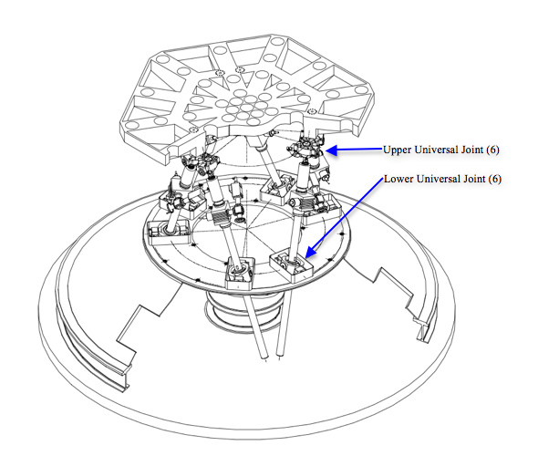
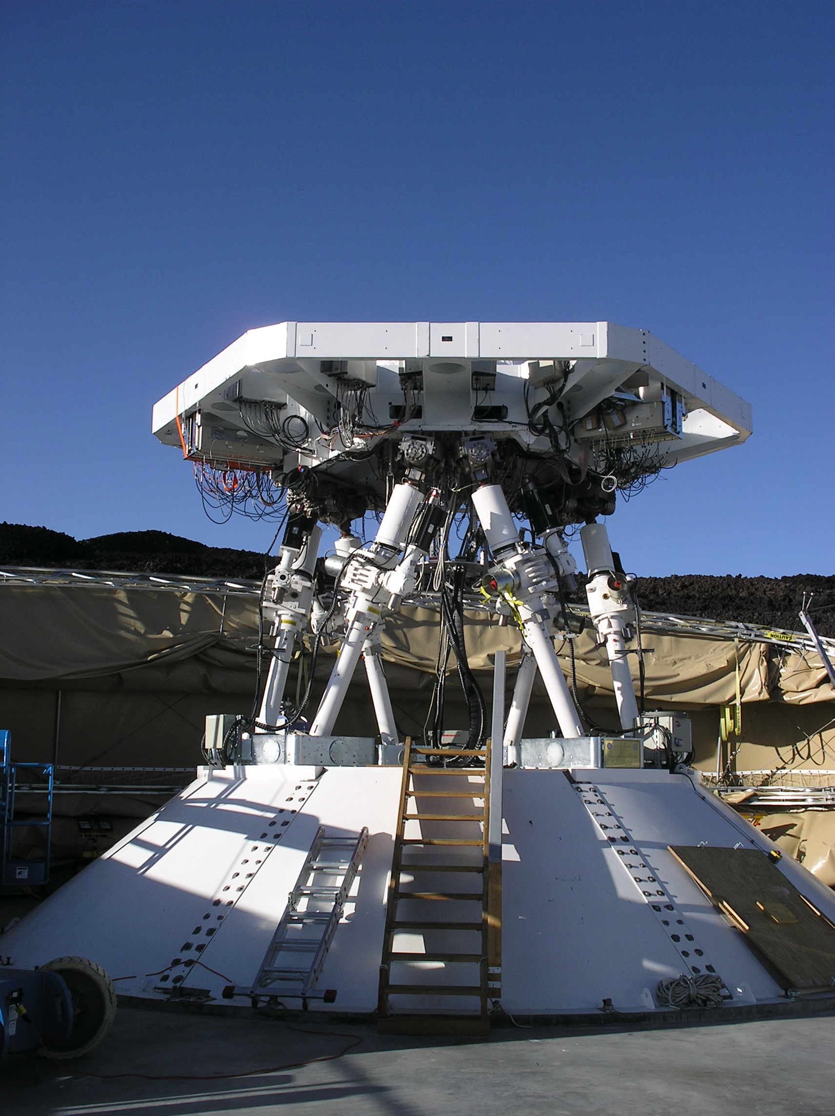
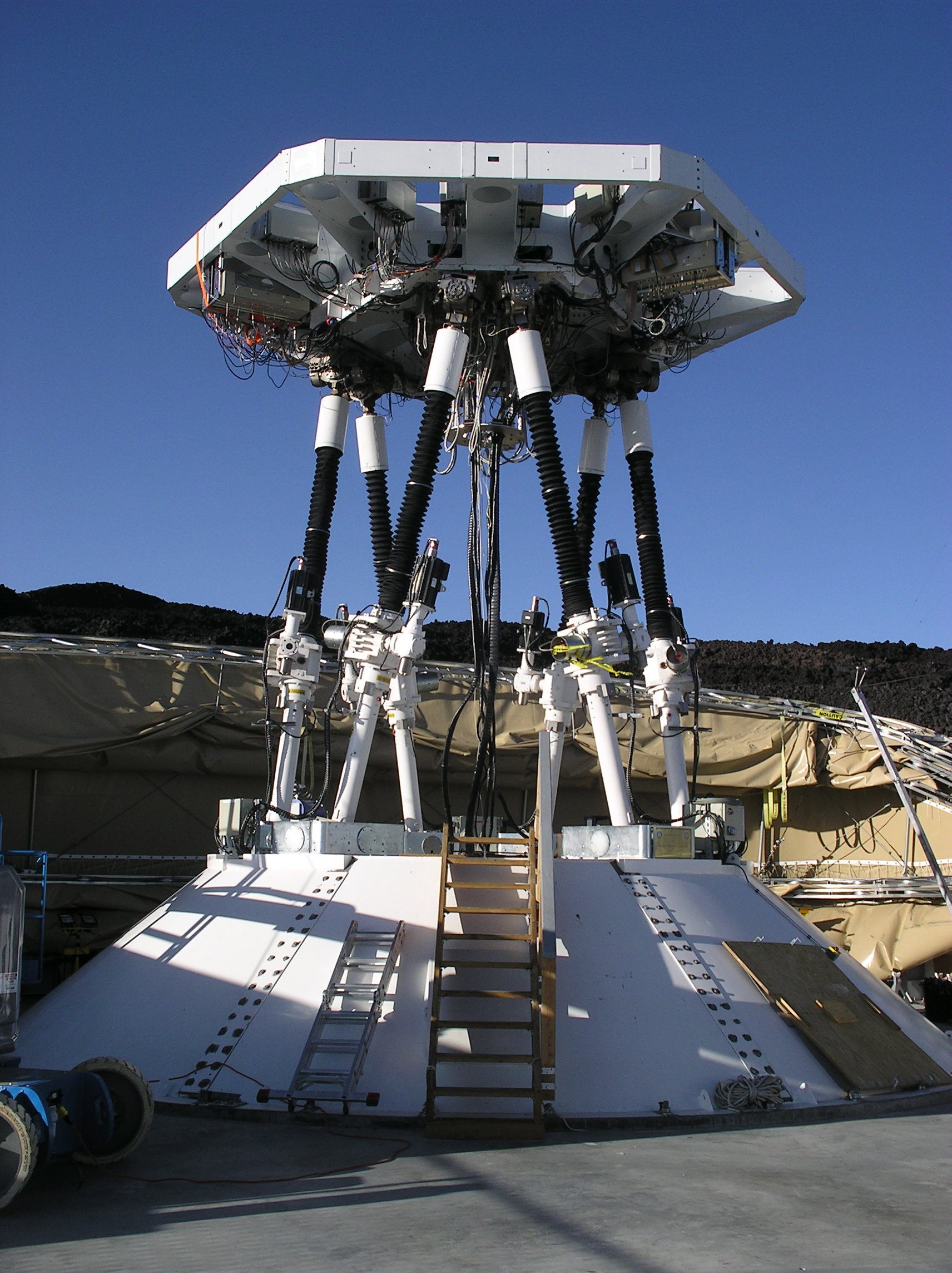
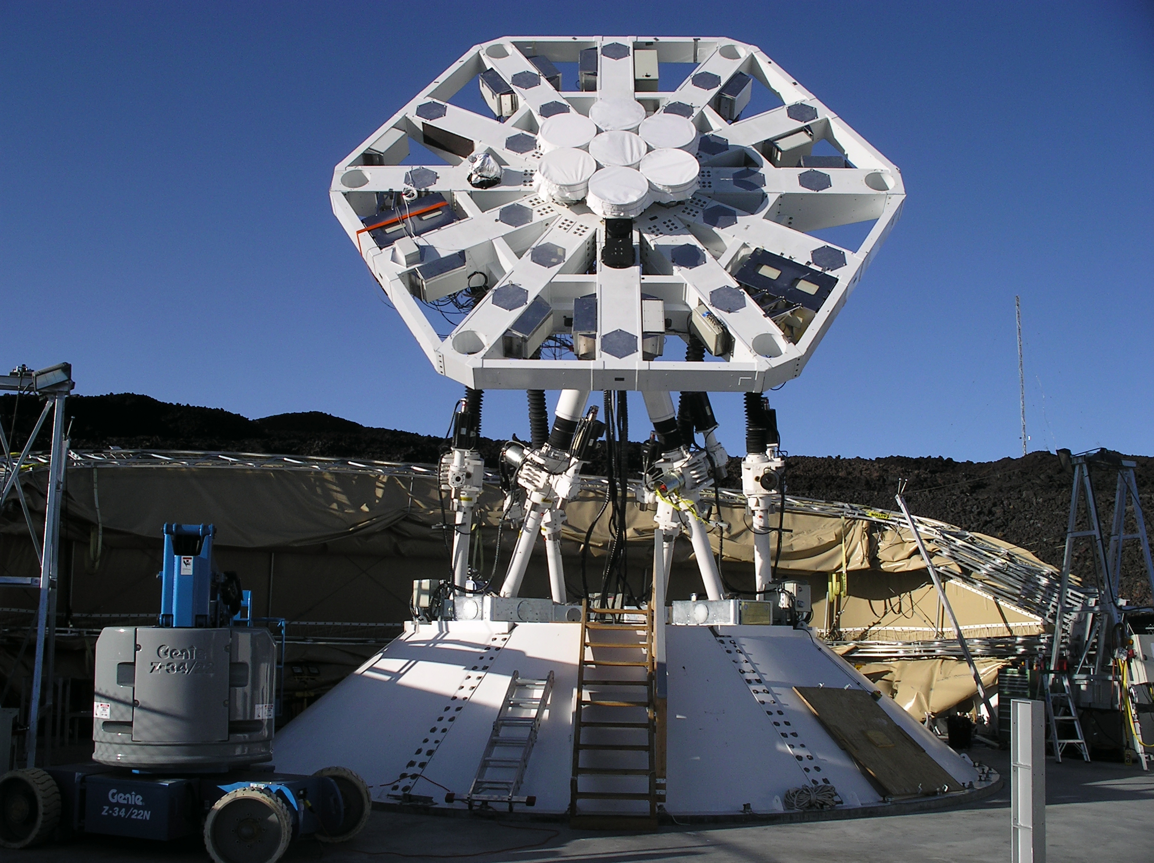
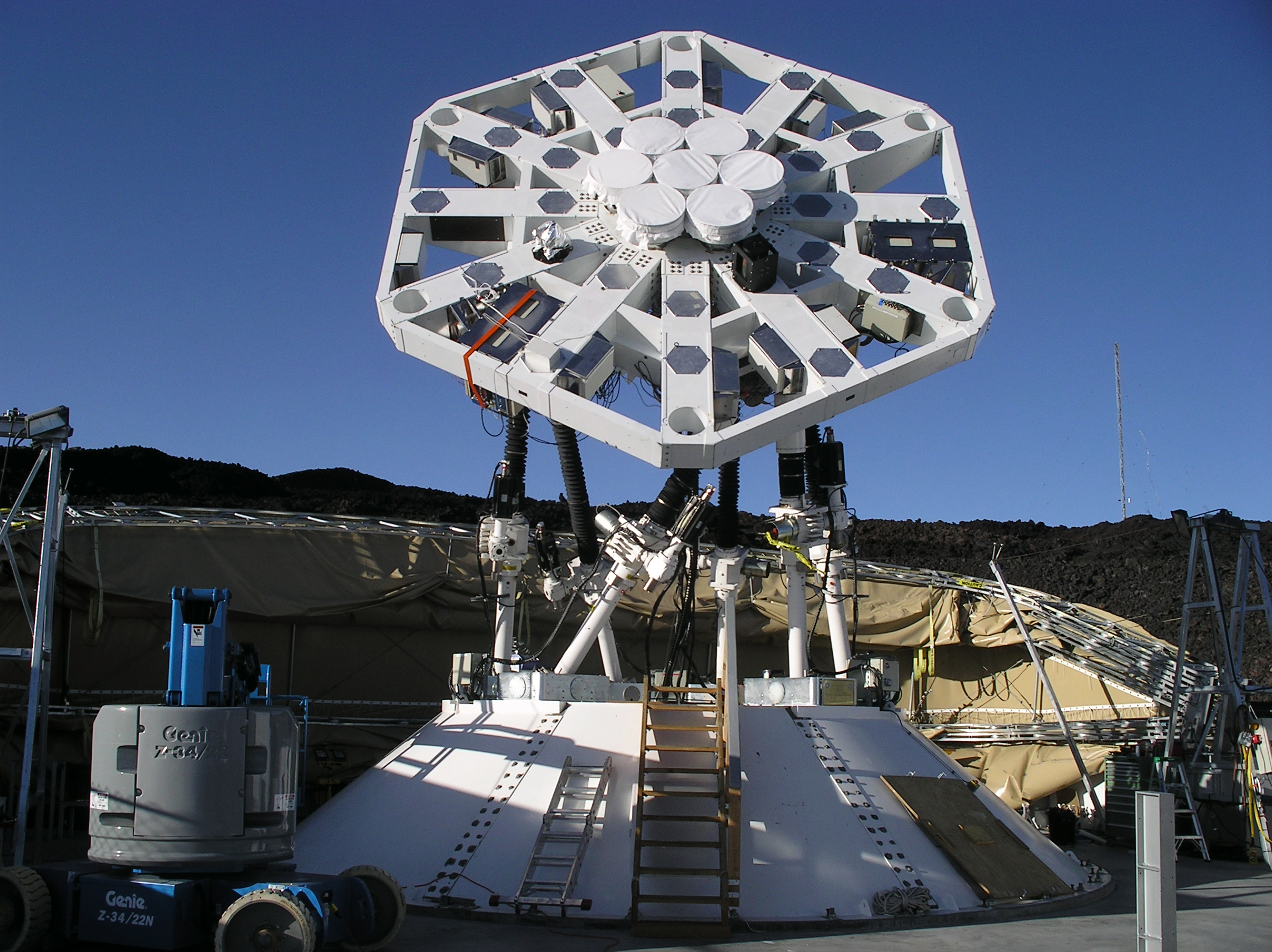
The hexapod mount is probably the most distinctive characteristic of the YTLA (formerly AMiBA) telescope. Structurally, it is very simple -- a platform manipulated by six actuators. By controlling the lengths of the actuators, one could point the platform toward a large portion of the sky. In addition, it provides the capability of platform rotation. Its design is driven by the requirement for having a lightweight structure which can be easily and quickly dismantled and shipped to another site for possible relocation, and the need of having direct access to the receivers on the platform for maintenance. The targeted science defines the range of the interferometer baseline lengths, leading to a 6-meter platform. Array configurations with maximum baselines require a pointing accuracy of ~0.2'. Based on these considerations, a hexapod mount with CFRP platform was chosen. In articular, for a hexapod mount no elevation counterweight and no azimuth bearing are needed and the access to the receivers and correlator from beneath the platform is straight forward. (Koch PM et al., 2009) The YTLA (formerly AMiBA) hexpod and its control system was fabricated by Vertex Antennentechnik GmbH, Duisburg, Germany. Key components in the actual system are the upper and lower universal joints requiring high stiffness and large travel ranges, the stiffness of the support cone to minimize its influence on the pointing error and finally the pointing error model itself to meet the desired 10' pointing accuracy. We stress here that the YTLA (formerly AMiBA) is currently the largest hexapod telescope. (Huang Y-D et al., 2011) The figures show YTLA (formerly AMiBA) in stow and neutral positions, respectively, and in two positions with various platform polarizations (hexpol).
The platform was manufactured by Composite Materials Applications (CMA) in Tucson, Arizona, USA. Driven by the same requirement of prompt relocation, the 6-meter platform was designed with a segmented approach in mind. There are totally 7 segments to compose the single YTLA (formerly AMiBA) platform. It is convenient for transportation. However, we eventually discovered that the segmented-platform is not stiff enough to hold up to our original specifications. In addition, due to safety considerations, a steel interfacing structure was implemented between the CFRP platform and the hexapod to ensure an overall integrated structure. The platform/hexapod has been surveyed using a photogrammetric method to study the surface flatness. Further simulation and analysis concludes that the interaction loading between platform and the hexapod actuators is the dominant factor affecting the platform deformation While the 7-element array occupied only the central part of the platform, where deformation was within tolerance. The 13-element array suffered significant loss due to phase incoherence. The deformation was then carefully measured and modeled using photogrammetry data and the relative change of pointing error from two optical telescopes mounted on the platform. This method successfully recovered the geometrical delay due to deformation and greatly reduced the loss. |
>> ASIAA

© Institute of Astronomy and Astrophysics, Academia Sinica, All Rights Reserved.
Contact: web asiaa.sinica.edu.tw | Privacy and Security Policy
Contact: web